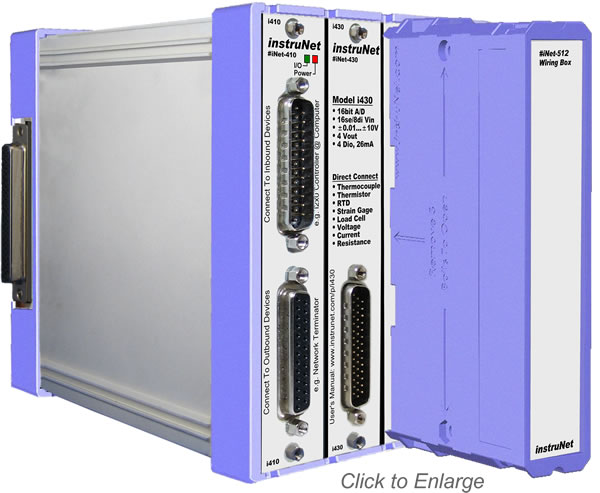
The i512 Sensor Wiring Box bolts to i60x/i4xx hardware, and provides the following features:
Screw Terminals
to which one can attach external signals to Hd44 connector
Enclosure box for end user installed wires and shunt resistors
The i512 can NOT do thermocouple measurements. To measure thermocouples one needs an i510.
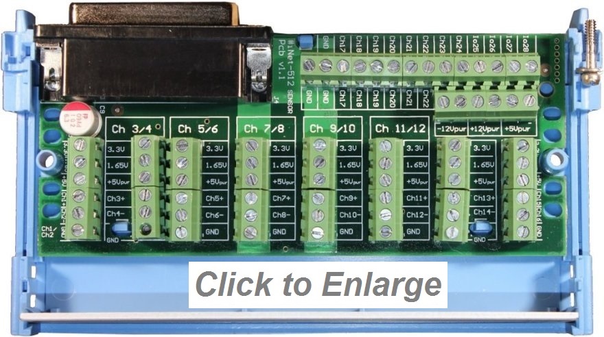
The pictures to the right show an open i512. Wires can be routed through both top and bottom windows in the plastic box.
The i51x is of clamshell design with identical top and bottom plastic halves that mate via 3 bolts.
Two captive 4-40 bolts secure the i51x to any i4xx card that has an Hd44 male connector.
The i512 is 7 x 2.5 x 13 cm in size (2.7" x 1" x 5.3", d/w/h).
Several Different Wiring Boxes
Several different i51x wiring boxes are available. For a summary of each, click
here.
Voltage References
Many i4xx/i60x devices provide a 3.3V reference voltage that is used to power sensors. The i512 routes this to the "3.3V" screw terminal in each terminal bank.
Also, the i512 has an internal amplifier with a voltage gain of 0.5 that takes this voltage and converts it to
a signal that is half the voltage (e.g. 1.65V = 3.3V/2 = vRef/2, 1mA). This can be used in
quarter and half bridge measurements where one needs to route half the voltage reference into one of the
input terminals (e.g. Vin-).
Vref/2 cannot be used to power sensors since it is only capable of suppling 1mA of current.
Above photo shows i512
bolted to i4xx Card
Above photos show open i512.
One of 8 banks of screw terminals
Wiring to Screw Terminals
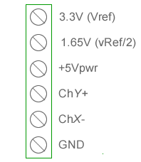
The i512 Wiring box provides 8 banks of screw terminals. Each bank provides
access to 3.3Vref, 1.65Vref (vRef/2), 5Vpwr, Ch+, Ch- and GND; as shown to the right.
Each bank is connected to channels 1/2, 3/4 .. 15/16.
To see how these are labeled on the actual pcb, click
here.
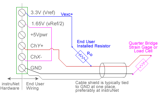
Wiring i512 to a QUARTER (¼) Bridge Sensor
The i512 can wire to a quarter bridge sensor (e.g. strain gage or load cell) with the help of one
user supplied bridge completion resistor, as illustrated below. For a list of available resistors,
click here.
The i512's vRef/2 (e.g. 1.65V) signal forms one side of the bridge,
and the other is formed by the end user completion resistor and sensor.
When working with a ¼ bridge sensor and the i512, one only needs 1 additional end user completion resistor, whereas
other wiring boxes (e.g. i510, i511, i100) require 3 additional resistors.
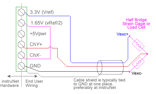
Wiring i512 to a HALF (½) Bridge Sensor
The i512 can wire to a half bridge sensor (e.g. strain gage or load cell), as illustrated below.
No external end user resistors are required when working with half bridge sensors and the i512 wiring box.
The i512's vRef/2 (e.g. 1.65V) signal forms one side of the bridge,
and the sensor's two resistors form the other side. Other wiring boxes (e.g. i510, i511, i100) required 2 additional
end user resistors to complete the bridge, and are therefore more
cumbersome than the i512 when working with ½ bridge sensors.
 Hidden
Hidden
Hidden
Hidden
Hidden
Hidden
Hidden