instruNet i60x Datasheet
Miniature USB Data Acquisition System Attaches Directly to Sensors
Miniature USB Data Acquisition System Attaches Directly to Sensors
|
|
|
|
|
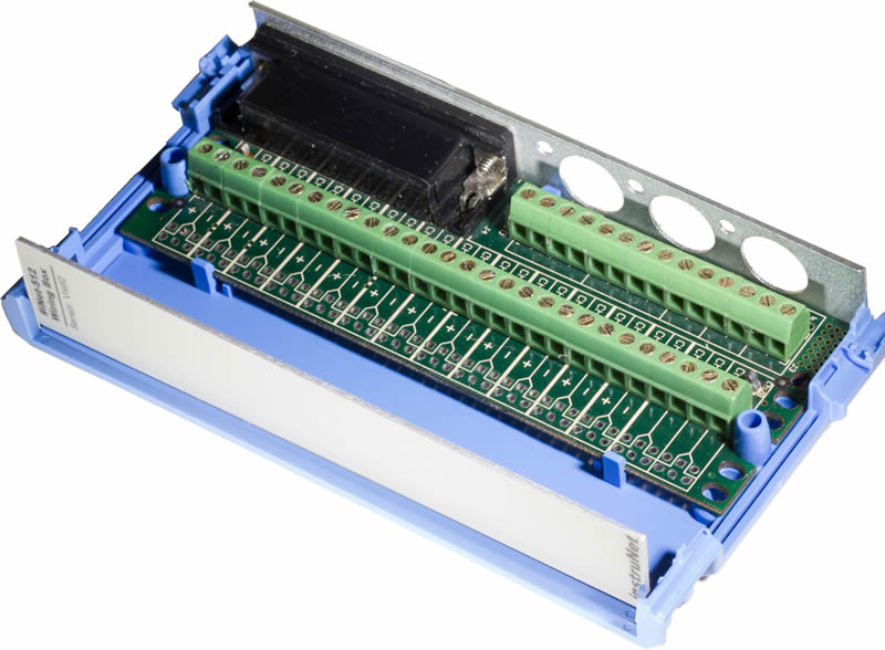
| Optional i51x Wiring Box |
 |
 |
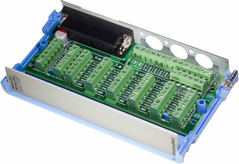 |
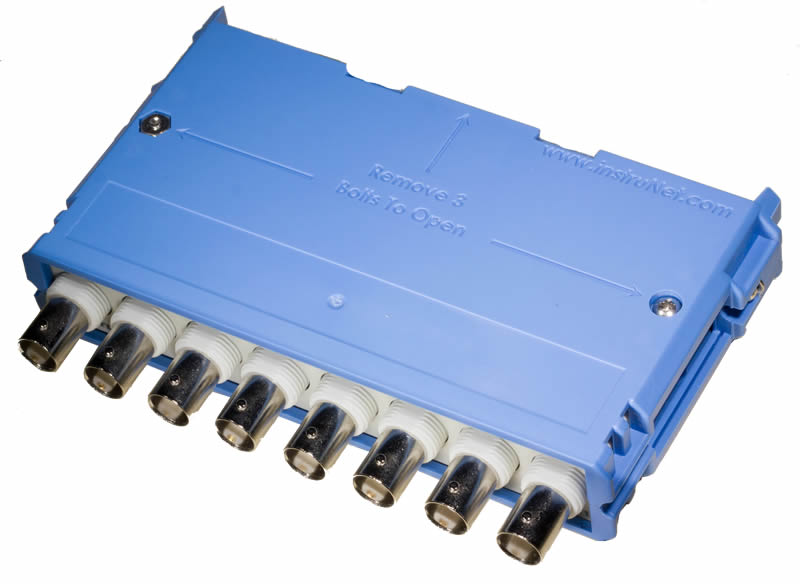
| i510 Low Cost Wiring Box | i511 BNC Wiring Box | i512 Wiring Box |
| Optional Accessories |
 |
 |
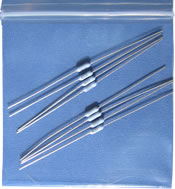 |
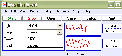
| instruNet World PLUS Software (iW+) | Application Software | Shunt Resistors |
| How to Connect Sensors |
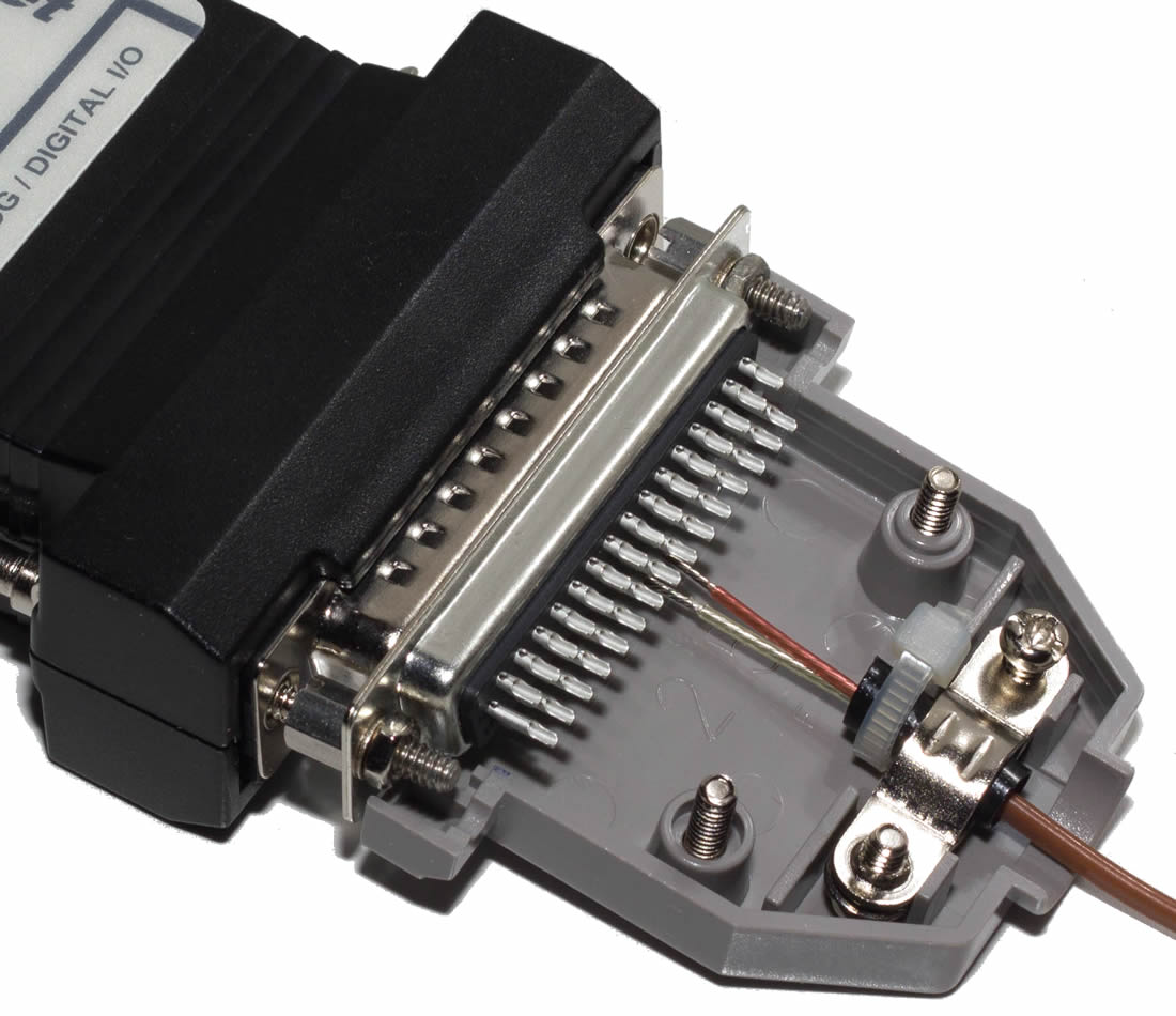 |
 |
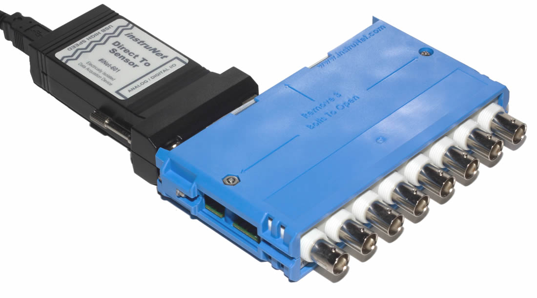 |
| Attach Directly to Hd44 Connector | Attach i60x to i51x Wiring Box | Attach to i511 BNC Wiring Box |
| What's Included in the Box? |
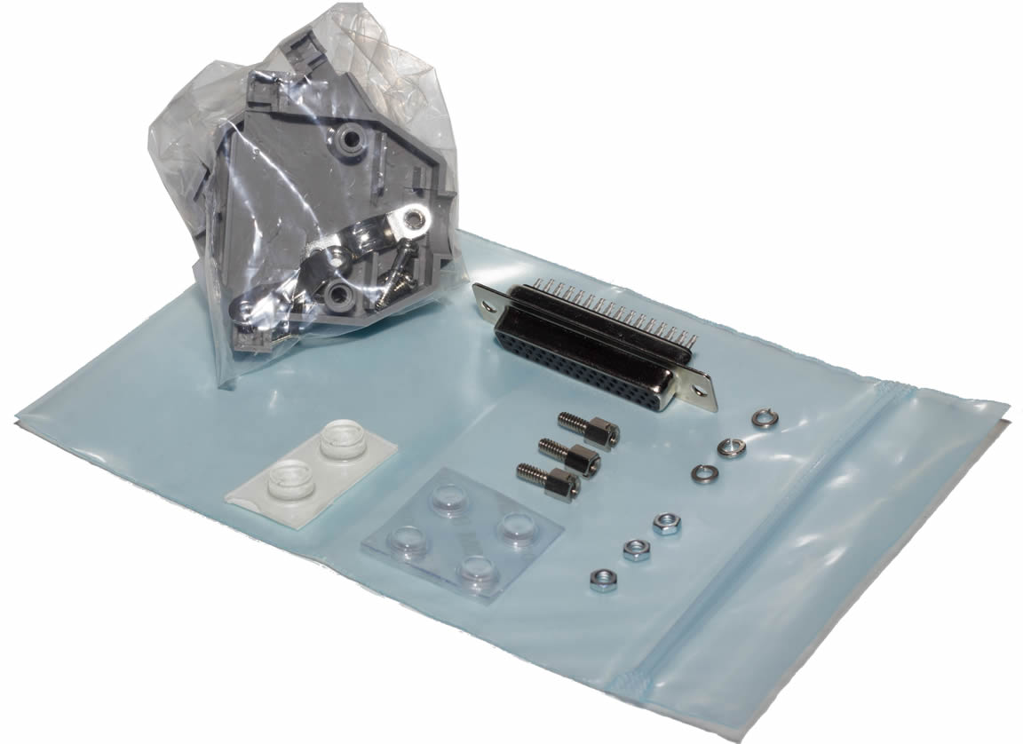 |
 |
 |
|
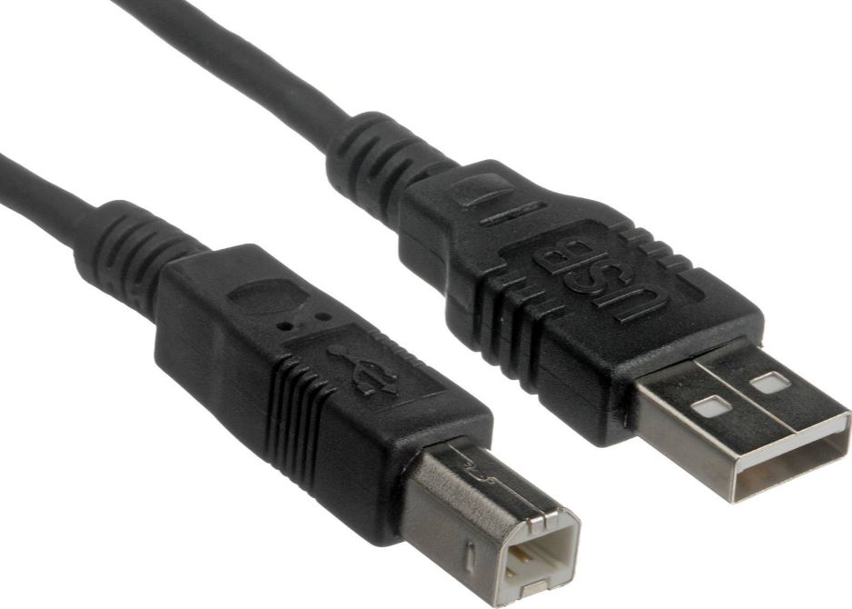
| i60x Device | i60x hardware Kit | instruNet World Software CD | 10ft (3m) USB Cable |
| Subjects Discussed in this Datasheet, iNet-600 & iNet-601 |
- Analog Voltage Input (A/D), Electrical Specifications, Software Interface
- 4x Digital I/O (4mA sink/source, 0 to 3.3V), Electrical Specifications, Software Interface
- I/O Software Channels
- Hd44 Connector Pins
- Power Available to End User
- Physical/Environmental Specifications
- Voltage Measurement Absolute Accuracy Specifications
- Voltage Measurement Drift Errors
- Thermocouple Measurement Absolute Accuracy Specifications
- Thermistor Measurement Absolute Accuracy Specifications
- RTD Measurement Absolute Accuracy Specifications
- Load Cell Measurement Absolute Accuracy Specifications
- Strain Gage Measurement Absolute Accuracy Specifications
- Potentiometer Measurement Absolute Accuracy Specifications
- Current Measurement Absolute Accuracy Specifications
- Resistance Measurement Absolute Accuracy Specifications
| Analog Voltage Input (A/D), iNet-600 & iNet-601 |
| Parameter | Specifications19 | Notes |
| Description | 16se/8di Voltage Input Channels with extremely accurate 24-bit A/D Converter29 | This A/D module provides 16se/8di voltage input channels (Ch#1...#16), each of which are independently software programmable with Windows software that support the direct connection to many common sensor types |
| Absolute Accuracy | Specified | Error components (i.e. INL, DNL, linearity, noise, temperature drift66 , time stability) are summed and specified as "Absolute Accuracy" with the following supported sensors (click for accuracy and maximum sample rate): Voltage, Thermocouple, Thermistor, RTD, Load Cell30, Strain Gage30, Potentiometer, Current, Resistance |
| Voltage Ranges | ±20mV ... ±10V | Voltage input range on each channel is independently software programmable to one of: ±20mV, ±40mV, ±80mV, ±150mV, ±300mV, ±600mV, ±1.2V, ±2.5V, ±5V, ±10V |
| Internal A/D | 24-bit | Internal 24-bit A/D Converter29 resolves voltage input range to ±8.4M digital value. |
| Sensors | Direct Connect | Each of the 8 differential channels support the direct connection to the following sensor types (click for Wiring Diagram and Setup Instructions): Voltage, Thermocouple, Thermistor, RTD, Load Cell30, Strain Gage30, Potentiometer, Current, Resistance |
| Channel Amplifiers | Software Programmable | Each channel provides the following software programmable parameters: A/D Signal-Averaging-Per-Point (0 ... 100mSec)3 , Sample-Rate (samples-per-second-per-channel)17 , Digital IIR Filter (LowPass, HighPass, BandPass, or BandStop)55 , Voltage Measurement Range (±20mV...±10V)1 , Sensor Type13 , and Single-Ended or Differential Wiring |
| Wiring | Single-Ended or Differential | Single-ended (SE) wiring involves measuring the voltage between the input pin and instruNet Ground; whereas Differential (DI) wiring involves measuring the voltage between two input pins |
| Protected Voltage | -30 to +30V | Short any combination of voltage input channels to external -30 to +30V power source (i.e. capable of high current), instruNet power on or off, any duration, without damage |
| Bandwidth | Depends on Voltage Range | See absolute accuracy specification tables below (e.g. Voltage Accuracy) for bandwidth details |
| RFI Filter | 13 KHz RFI filter on ≤ ±150mVrange |
RFI filter is a low pass filter that rejects high frequencies that could cause small measurement errors if left unfiltered |
| Digital Filter | LowPass, HighPass, BandPass, or BandStop | Each channel provides optional digital IIR lowpass, highpass, bandpass and bandstop filters with independent software programmable cut-off frequency, minimum dB stopband attenuation, maximum dB passband attenuation, and filter type (e.g. Elliptic, Chebyshev B, Chebyshev S, and Butterworth). Number of poles/zeros (i.e. "filter order") is programmable between 2 and 3255 . |
| Maximum Sample Rate17 | 160Ks/sec/aggregate | Digitize70 at a maximum sample rate of 160K sample/sec for 1 channel on largest voltage input range. More channels at same voltage input range involves slower rates, e.g. 12Ks/sec per channel for 2 channels, 6Ks/sec/ch for 4 channels, and 3Ks/sec/ch for 8 channels. For a details on maximum sample rate and bandwidth with different voltage input ranges, sensor types, and a/d averaging61 ; see absolute accuracy specification tables below (e.g. Voltage Accuracy). Sample rate is set accurate to 50 ppm (e.g. user specifies 20000 s/sec yet system actually digitizes at 20001 s/sec). Minimum sample rate is 0.015 samples/sec/ch. |
| Sensor Excitation | Included | Excitation power (+3.3V ±0.2V, <80mA, 28mA per sensor max) is provided for sensors30, along with other End User Power voltages. This 3.3V, which is referenced to instruNet Ground, is automatically readback by A/D when calculating sensor values. |
| Electrical Specifications, Analog Voltage Input, iNet-600 & iNet-601 |
| Parameter | Specifications19 | Notes |
| Common Mode Voltage | -10 to +10V | All voltage input pins must be driven with a voltage between -10 and +10V, with respect to instruNet ground. i600 ground is connected to computer ground via USB bus (which is connected to Earth ground via computer power supply plug 3rd prong). Alternatively, i601 ground is electrically isolated from computer ground. |
| Crosstalk | < -80dB typ | Crosstalk from one channel to another depends on sample rate and frequency of applied signal, and is typically < -80dB; i.e. -80dB = 20 * log (1 / 10000). For example, one can apply a 10Hz 10Vpp sinewave to Ch1 on the ±5Vrange, apply 0 Volts DC to Ch3 on the ±2.5Vrange, digitize both at the maximum sample rate, and see < 1mVpp sinewave on Ch3, in a typical case. The amplitude of this sinewave would decrease with slower sample rates, and increase with higher sinewave frequencies. |
| Input Coupling | DC | Measure constant DC voltage or dynamic AC waveform with absolute voltage accuracy |
| Input Impedance | 100MΩ | Internal 100MΩ resistor (5% accuracy) between input pin and instruNet ground reduces fluctuating measurements when input pin is left unconnected |
| Current Pump | 35 pC max | Internal multiplexors pump a small amount of current out voltage measurement pin and into the end user circuit when channels switch. This is normal for multiplexors (they all do this), and is automatically mitigated when doing sensor measurements by waiting for current to dissipate before taking the measurement. If you don't like multiplexors, or need fast sample rates with low level signals; please see i423 which routes inputs to instrumentation amplifiers instead of multiplexors. |
| Input leakage current | 4.5 nA max at 37°C | This is a small current that flows out the voltage input pin and into the end user circuit. It has little effect unless measuring small voltages (e.g. expecting accuracy better than ±100uV) with a high source impedance (e.g. > 2K Ω). Maximum leakage is 4.5 nA at 37°C, and 2.3 nA at 25°C. |
| Input Circuit | Multiplexer | Voltage input pin connects directly to internal protected multiplexer IC |
| Common Mode Rejection Ratio | ≥ 110dB | CMRR is the amount of rejection of a common signal that is present on both inputs of a differential measurement. Theoretically, it should not be measured because the differential measurement looks at the voltage between two pins; however small internal imbalances cause a small error, which is specified here with a DC to 60Hz common mode signal. |
| Calibration | Software Control | instruNet hardware is calibrated66 when the system is reset (i.e. press RESET button, load .prf configuration file, or start instruNet software), and when the system is software calibrated (i.e. press CALIBRATE button, issue software calibrate command, or set up software to calibrate every X minutes59 ). |
| Front End Schematics | Published | Schematics: i60x Hd44 Schematic, i60x Multiplexer Schematic |
| Software Interface, Analog Voltage Input, iNet-600 & iNet-601 |
| Parameter | Specifications19 | Notes |
| Software Interface | Windows Compatible | instruNet Scalar I/O and High Speed I/O60 interface subroutines execute on Windows Computer via instruNet World, Visual Basic, C, Labview, or DasyLab software. Scalar I/O reads or writes 1 value at a time; whereas High Speed I/O reads or writes multiple values (i.e. a waveform) at a fixed rate (i.e. sample rate). |
| Maximum # of Channels | Up to 256 | instruNet system (iNet32/64.dll ≥ v3.0) supports simultaneous high speed I/O to/from computer with 1 to 256 I/O channels70 |
| Maximum Waveform Size | Limited by Computer | Continuously digitize into Windows computer RAM or into file on Windows computer hard disk62 . Maximum file size is limited by available space on hard disk. Data consumes 4 bytes per point. |
| Scalar I/O Benchmark | 50 to 300uSec typ | Scalar I/O60 typically requires 50 to 300uSec to read 1 value from 1 voltage input channel with 0 mSec of a/d averaging. This increases by the amount of a/d averaging (e.g. 1050 to 1300uSec for 1mSec of a/d averaging) |
| Software Channels | Ch1 Vin+ ... Ch16 Vin- | Channels #1...#16: SE/DI voltage inputs, ±20mV...±10V |
| Connector Pins | One pin per bit | Signals are available at Hd44 connector pins: #1...#16217 |
| Ground Reference | Hd44 Pins 29/42/43/44 | i600 ground is connected to computer ground via USB bus (which is connected to Earth ground via computer power supply plug 3rd prong). Alternatively, i601 ground is electrically isolated from computer ground. |
| 4x Digital I/O, 4mA sink/source, iNet-600 & iNet-601 |
| Parameter | Specifications19 | Notes |
| Description | 4 Bidirectional Digital I/O | The 4mA sink/source digital I/O port consists of 4 individual TTL-compatible lines (Ch#25...#28), each of which can be configured as: input or output bit. When configured as an input, a channel can be used to sense a digital high (2 to 5.5 Volts) or digital low (0V to 0.8Volts). When configured as an output, a channel can be set high (e.g. >2V) or low (e.g. <0.8V). These I/O pins are short-circuit protected against high voltages up to 6.0V and down to -6.0V. |
| Function | input or output bit | Each bit is independently software programmed as an input or output |
| TTL Compatible | Yes | Supports 0.8V for logic 0 and 2V for logic 1, which is typical for TTL |
| 3.3V CMOS Compatible | " | Supports 1.1V (3.3V*.35) for logic 0 and 2.3V (3.3V*.7) for logic 1, which is typical for digital Cmos powered by 3.3V |
| Drive Relay Directly | " | Wire one side of external relay coil to power supply (e.g. 5V), wire other side to I/O pin, and output logic 0 to turn on relay |
| Detect Switch Closure | " | Wire one side of external switch to gnd, wire other side to I/O pin, input logic 0 when switch is closed, and input logic 1 when switch is open |
| Electrical Specifications, Digital I/O, iNet-600 & iNet-601 |
| Parameter | Specifications19 | Notes |
| Working Voltage | 0 to +5.5V | Functions properly when working with 0 to +5.5V between the I/O pin and instruNet gnd, where each bit is set up as an input or output |
| Protected Voltage | -6 to +6V | Short any combination of I/O pins to external -6 to +6V power source (i.e. capable of high current), set up as input or output (0 or 1), instruNet power on or off, without damage |
| Fuse | Auto-Reset, 4 Milliamp | Internal fuse on each I/O pin opens during > 4mA over-current condition, and automatically closes otherwise |
| "0" Input Voltage | 0 to +0.8V | Applying 0 to +0.8V is read as logic 0 when I/O pin is configured as input |
| "0" Input Current | Amps = Vin / 50K | External signal must pull up internal 50.0K resistor (which is connected to GND). |
| "1" Input Voltage | 2V to +5.5V | Applying 2V to 5.5V is read as logic 1 when I/O pin is configured as input. If left unconnected this pin floats to 0V. |
| "0" Output Voltage | < 0.7V @ 2mA, < 0.9V @ 4mA |
I/O pin configured as an output sinks current low to 0.3V...0.7V with 0 to 2mA load; or sinks low to 0.3V...0.9V with 0 to 4mA load |
| "1" Output Voltage | > 2.4V @ 2mA, > 2.2V @ 4mA |
I/O pin configured as an output sources current high to 2V...3.3V with 0 to 4mA load. |
| Software Interface, Digital I/O, iNet-600 & iNet-601 |
| Parameter | Specifications19 | Notes |
| Software Interface | Windows Compatible | instruNet Scalar I/O and High Speed I/O60 interface subroutines execute on Windows Computer via instruNet World, Visual Basic, C, Labview, or DasyLab software. Scalar I/O reads or writes 1 value at a time; whereas High Speed I/O reads or writes multiple values (i.e. a waveform) at a fixed rate (i.e. sample rate). |
| Maximum # of Channels | Up to 256 | instruNet system (iNet32/64.dll ≥ v3.0) supports simultaneous high speed I/O to/from computer with 1 to 256 I/O channels70 |
| Scalar I/O Benchmark | 50 to 300uSec typ | Scalar I/O60 typically requires 50 to 300uSec to R/W 1 value to/from 1 bit or a bank of multiple I/O bits |
| Bit or Bank Control | Yes | Either R/W one bit (0 or 1 value) at a time, or R/W multiple bits within one bank (e.g. 0...255 value with one 8bit bank) |
| Latching I/O | " | Internal register reads all input bits within one bank at same time, and updates all output bits within one bank at same time |
| Bit Software Channels | Ch25 Dio ... Ch28 Dio |
Channels #25...#28: digital I/O bits, 0 or 1 value, scalar input/output, no high speed i/o, 4mA sink/source |
| Bank Software Channels | Uio25_28 In Uio25_28 Out |
Channel #29: bank of 4 bits, 0...15 value, scalar input/output, no high speed i/o Channel #30: bank of 4 bits, 0...15 value, scalar input/output, no high speed i/o |
| Connector Pins | One pin per bit | Signals are available at Hd44 connector pins: #25...#28217 |
| Ground Reference | Hd44 Pins 29/42/43/44 | i600 ground is connected to computer ground via USB bus (which is connected to Earth ground via computer power supply plug 3rd prong). Alternatively, i601 ground is electrically isolated from computer ground. |
| I/O Software Channels, iNet-600 & iNet-601 |
| ChNum | Name | Channel Type | Hd44 Pin(s) | Description | Scalar I/O Support |
High Speed Digitize Support |
| #1 | Ch1 Vin+ | SE/DI Voltage Input | 1, 2 | ±20mV...±10V | input | input |
| #2 | Ch2 Vin- | SE Voltage Input | 2 | " | " | " |
| #3 | Ch3 Vin+ | SE/DI Voltage Input | 3, 4 | " | " | " |
| #4 | Ch4 Vin- | SE Voltage Input | 4 | " | " | " |
| #5 | Ch5 Vin+ | SE/DI Voltage Input | 5, 6 | " | " | " |
| #6 | Ch6 Vin- | SE Voltage Input | 6 | " | " | " |
| #7 | Ch7 Vin+ | SE/DI Voltage Input | 7, 8 | " | " | " |
| #8 | Ch8 Vin- | SE Voltage Input | 8 | " | " | " |
| #9 | Ch9 Vin+ | SE/DI Voltage Input | 9, 10 | " | " | " |
| #10 | Ch10 Vin- | SE Voltage Input | 10 | " | " | " |
| #11 | Ch11 Vin+ | SE/DI Voltage Input | 11, 12 | " | " | " |
| #12 | Ch12 Vin- | SE Voltage Input | 12 | " | " | " |
| #13 | Ch13 Vin+ | SE/DI Voltage Input | 13, 14 | " | " | " |
| #14 | Ch14 Vin- | SE Voltage Input | 14 | " | " | " |
| #15 | Ch15 Vin+ | SE/DI Voltage Input | 15, 16 | " | " | " |
| #16 | Ch16 Vin- | SE Voltage Input | 16 | " | " | " |
| #25 | Ch25 Dio | One Dio Bit | 25 | 0 or 1, 4mA sink/source | input/output | no high speed i/o |
| #26 | Ch26 Dio | " | 26 | " | " | " |
| #27 | Ch27 Dio | " | 27 | " | " | " |
| #28 | Ch28 Dio | " | 28 | " | " | " |
| #29 | Uio25_28 In | Group of Dio Bits | 25...28 | 0...15 | " | " |
| #30 | Uio25_28 Out | " | " | " | " | " |
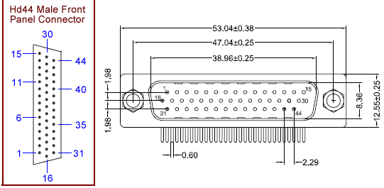
| Hd44 Connector Pins, iNet-600 & iNet-601 |
| Hd44 Pin# | Pin Name | Pin Type | Description |
| #1 | Ch1 Vin+ | SE/DI+ Voltage In | Supported Sensors: Voltage, Thermocouple, Thermistor, RTD, Load Cell30, Strain Gage30, Potentiometer, Current, Resistance |
| #2 | Ch2 Vin- | SE/DI- Voltage In | " |
| #3 | Ch3 Vin+ | SE/DI+ Voltage In | " |
| #4 | Ch4 Vin- | SE/DI- Voltage In | " |
| #5 | Ch5 Vin+ | SE/DI+ Voltage In | " |
| #6 | Ch6 Vin- | SE/DI- Voltage In | " |
| #7 | Ch7 Vin+ | SE/DI+ Voltage In | " |
| #8 | Ch8 Vin- | SE/DI- Voltage In | " |
| #9 | Ch9 Vin+ | SE/DI+ Voltage In | " |
| #10 | Ch10 Vin- | SE/DI- Voltage In | " |
| #11 | Ch11 Vin+ | SE/DI+ Voltage In | " |
| #12 | Ch12 Vin- | SE/DI- Voltage In | " |
| #13 | Ch13 Vin+ | SE/DI+ Voltage In | " |
| #14 | Ch14 Vin- | SE/DI- Voltage In | " |
| #15 | Ch15 Vin+ | SE/DI+ Voltage In | " |
| #16 | Ch16 Vin- | SE/DI- Voltage In | " |
| #17 | Not Used | Not Used | |
| #18 | " | " | " |
| #19 | " | " | " |
| #20 | " | " | " |
| #21 | " | " | " |
| #22 | " | " | " |
| #23 | " | " | " |
| #24 | " | " | " |
| #25 | Ch25 Dio | One Dio Bit | digital I/O bits, 0 or 1 value, scalar input/output, no high speed i/o, 4mA sink/source, 0 to 3.3V |
| #26 | Ch26 Dio | " | " |
| #27 | Ch27 Dio | " | " |
| #28 | Ch28 Dio | " | " |
| #29 | Gnd | instruNet Ground | i600 ground is connected to computer ground via USB bus (which is connected to Earth ground via computer power supply plug 3rd prong). Alternatively, i601 ground is electrically isolated from computer ground. |
| #30 | Internal_30 | Internal Use Only | Pin is used by manufacturer for product testing, please do not touch |
| #31 | Internal_31 | " | " |
| #32 | Internal_32 | " | " |
| #33 | Internal_33 | " | " |
| #34 | 3.3Vref | +3.3V ±0.2V, <80mA | Power Available to End User |
| #35 | " | " | " |
| #36 | 5Vpwr | +5V ±0.6V, <8mA | Power Available to End User |
| #37 | " | " | " |
| #38 | 12Vpwr | +15V ±1.2V, <4mA | Power Available to End User |
| #39 | " | " | " |
| #40 | -12Vpwr | -15V ±1.2V, <4mA | Power Available to End User |
| #41 | " | " | " |
| #42 | Gnd | instruNet Ground | i600 ground is connected to computer ground via USB bus (which is connected to Earth ground via computer power supply plug 3rd prong). Alternatively, i601 ground is electrically isolated from computer ground. |
| #43 | " | " | " |
| #44 | " | " | " |
|
| Power Available to End User, iNet-600 & iNet-601 |
| Parameter | Specifications19 | Notes |
| Description | External Power | +3.3V, +5V, +15V, and -15V power (< 80mA) is available to the end user at several Hd44 Connector217 pins. |
| +3.3V Reference Pwr | +3.3V ±0.2V, <80mA30 | +3.3Vdc power available to end user at Hd44 connector pins 34 and 35 |
| +5V End User Pwr | +5V ±0.6V, <8mA | +5Vdc power available to end user at Hd44 connector pins 36 and 37 |
| +15V End User Pwr | +15V ±1.2V, <4mA | +15Vdc power available to end user at Hd44 connector pins 38 and 39 |
| -15V End User Pwr | -15V ±1.2V, <4mA | -15Vdc power available to end user at Hd44 connector pins 40 and 41 |
| Fuse | Auto-Reset | Internal fuse on each power voltage opens during over-current condition, and automatically closes otherwise. 3.3Vref has 0.25A fuse, 5Vpwr has 15mA/100Ω fuse, and ±15Vpwr has 7mA/470ohmΩ fuse. |
| Physical/Environmental Specifications, iNet-600 & iNet-601 |
| Parameter | Specifications19 | Notes |
| I/O Connector | HD44 male | High density 44 pin male connector217 (e.g. Astron #HD6C-44-AMAN-1G213 , click footnote for datasheet, outer shell is same size as DB25) |
| Wiring Box | Compatible | Compatible with the following optional wiring boxes: i510, i511, i512 |
| Physical Dimensions | 3.784" x 0.924" x 2.286" | For details, see i60x Mechanical Drawing |
| Operating Temp. | 1 to 70°C | Operate in temperature between 1°C and 70°C, no condensation |
| Storage Temperature | -20 to 70°C | Store in ambient temperature between -20°C and +70°C |
| Relative Humidity | ≤ 90% | Operate in humidity less than 90%, no condensation |
| Hot Plug & Play | Yes | One can attach device with power on or off, without damage |
| USB Interface | 2.0 | Transfer data to/from device at 480Mbits/sec |
| Safety | IEC, EN, UL, CSA | Designed to meet IEC 61010-1, EN 61010-1, UL 61010-1, CSA 61010-1 |
| Emissions | EN, CE, FCC | Designed to meet EN 61326 EMC Min Immunity, EN 55011 Emissions Group 1 Class A, CE, C-tick, ICES, and FCC Part 15 Emissions Class A |
| CE Compliance | Yes | Meets 73/23/EEC low-voltage safety, and 89/336/EEC electromagnetic compatibility |
| Specifications | Subject to change | All specifications are subject to change without notice |
| +5V USB Power, Max | +5V ±0.4V, ~433mA | Power drawn from USB bus, with max load from end user sensors |
| +5V USB Power, Typ | +5V ±0.4V, ~255mA | Power drawn from USB bus, with no load from end user sensors |
|
Voltage Measurement Absolute Accuracy Specifications, iNet-600 & iNet-601 |
| Voltage Range 1 |
Signal Averaging Per Point (mSec) 3 |
Absolute Accuracy (Max Gain + Offset Error) 38a |
Max Multi- Channel Aggregate Sample Rate (s/sec/agg) 18 |
Channel Switching Acquisition Time (uSec) 4 |
Analog Amplifier Bandwidth (KHz) 5 |
| ±10V | 0 mSec | ±(0.005% + 1569.9μV) | 33.40K | 29.9 | 315 |
| 0.1 mSec | ±(0.005% + 973.2μV) | 4.52K | 29.9 | 315 | |
| 1.0 mSec | ±(0.005% + 271.8μV) | 0.77K | 29.9 | 315 | |
| ±5V | 0 mSec | ±(0.005% + 709.4μV) | 33.40K | 29.9 | 315 |
| 0.1 mSec | ±(0.005% + 443.8μV) | 4.52K | 29.9 | 315 | |
| 1.0 mSec | ±(0.005% + 131.6μV) | 0.77K | 29.9 | 315 | |
| ±2.5V | 0 mSec | ±(0.005% + 374.2μV) | 25.49K | 39.2 | 315 |
| 0.1 mSec | ±(0.005% + 234.0μV) | 4.52K | 39.2 | 315 | |
| 1.0 mSec | ±(0.005% + 69.2μV) | 0.76K | 39.2 | 315 | |
| ±1.2V | 0 mSec | ±(0.005% + 197.3μV) | 25.26K | 39.6 | 315 |
| 0.1 mSec | ±(0.005% + 123.7μV) | 4.52K | 39.6 | 315 | |
| 1.0 mSec | ±(0.005% + 37.2μV) | 0.76K | 39.6 | 315 | |
| ±600mV | 0 mSec | ±(0.005% + 123.9μV) | 20.86K | 47.9 | 315 |
| 0.1 mSec | ±(0.005% + 91.5μV) | 4.27K | 47.9 | 315 | |
| 1.0 mSec | ±(0.005% + 22.4μV) | 0.75K | 47.9 | 315 | |
| ±300mV | 0 mSec | ±(0.005% + 90.9μV) | 20.71K | 48.3 | 315 |
| 0.1 mSec | ±(0.005% + 66.8μV) | 4.27K | 48.3 | 315 | |
| 1.0 mSec | ±(0.005% + 15.3μV) | 0.75K | 48.3 | 315 | |
| ±150mV | 0 mSec | ±(0.005% + 70.4μV) | 3.75K | 187.7 | 21 |
| 0.1 mSec | ±(0.005% + 22.8μV) | 2.65K | 187.7 | 21 | |
| 1.0 mSec | ±(0.005% + 11.4μV) | 0.69K | 187.7 | 21 | |
| ±80mV | 0 mSec | ±(0.005% + 49.3μV) | 3.75K | 193.6 | 21 |
| 0.1 mSec | ±(0.005% + 16.5μV) | 2.65K | 193.6 | 21 | |
| 1.0 mSec | ±(0.005% + 8.6μV) | 0.68K | 193.6 | 21 | |
| ±40mV | 0 mSec | ±(0.005% + 32.8μV) | 3.58K | 199.1 | 21 |
| 0.1 mSec | ±(0.005% + 11.7μV) | 2.56K | 199.1 | 21 | |
| 1.0 mSec | ±(0.005% + 6.7μV) | 0.68K | 199.1 | 21 | |
| ±20mV | 0 mSec | ±(0.006% + 32.1μV) | 3.58K | 198.3 | 21 |
| 0.1 mSec | ±(0.006% + 11.4μV) | 2.56K | 198.3 | 21 | |
| 1.0 mSec | ±(0.006% + 6.5μV) | 0.68K | 198.3 | 21 |
Voltage Specification Conditions, iNet-600 & iNet-601
|
Software Programmable Parameters Each channel provides the following independently programmable parameters:
More Information |
|
Voltage Measurement Drift Errors, iNet-600 & iNet-601 |
| Voltage Range 1 |
Absolute Accuracy (Max Gain + Offset Error) 38a |
Additional Error Per °C If Operate Hardware at >33°C or <13°C 7 | Additional Error Per Year if Not Factory Calibrate Hardware After 1Yr 9 | Additional Error per °C if not AutoCal after 1°C Hardware Change Since last AutoCal 8 |
| ±10V | ±(0.005% + 271.8μV) | ±0.0003%/°C | ±0.0012%/yr | ±(0.0003% + 1.8μV)/°C |
| ±5V | ±(0.005% + 131.6μV) | ±0.0003%/°C | ±0.0012%/yr | ±(0.0003% + 1.0μV)/°C |
| ±2.5V | ±(0.005% + 69.2μV) | ±0.0003%/°C | ±0.0012%/yr | ±(0.0003% + 0.7μV)/°C |
| ±1.2V | ±(0.005% + 37.2μV) | ±0.0003%/°C | ±0.0012%/yr | ±(0.0003% + 0.4μV)/°C |
| ±600mV | ±(0.005% + 22.4μV) | ±0.0003%/°C | ±0.0012%/yr | ±(0.0003% + 0.3μV)/°C |
| ±300mV | ±(0.005% + 15.3μV) | ±0.0003%/°C | ±0.0012%/yr | ±(0.0003% + 0.2μV)/°C |
| ±150mV | ±(0.005% + 11.4μV) | ±0.0003%/°C | ±0.0012%/yr | ±(0.0003% + 0.2μV)/°C |
| ±80mV | ±(0.005% + 8.6μV) | ±0.0003%/°C | ±0.0012%/yr | ±(0.0003% + 0.1μV)/°C |
| ±40mV | ±(0.005% + 6.7μV) | ±0.0003%/°C | ±0.0012%/yr | ±(0.0003% + 0.1μV)/°C |
| ±20mV | ±(0.006% + 6.5μV) | ±0.0004%/°C | ±0.0012%/yr | ±0.0004%/°C |
|
Thermocouple Measurement Absolute Accuracy Specifications, iNet-600 & iNet-601 |
| TC Type 13 |
Measurement Range 11 |
Voltage Range 1 |
Absolute Accuracy (±Max Error) 38w |
Max Multi- Channel Aggregate Sample Rate (s/sec/agg) 18 |
||
| J | -210 to 150°C | ±20mV |
|
2.56K | ||
|
i423 is faster | |||||
| -210 to 1200°C | ±80mV |
|
2.65K | |||
|
||||||
| K | -200 to 200°C | ±20mV |
|
2.56K | ||
|
||||||
| -200 to 1360°C | ±80mV |
|
2.65K | |||
|
||||||
| B | 251 to 1820°C | ±20mV |
|
2.56K | ||
|
||||||
|
||||||
|
||||||
| C | 0 to 1K°C | ±20mV |
|
2.56K | ||
| 0 to 2315°C | ±40mV |
|
2.56K | |||
| D | 0 to 1K°C | ±20mV |
|
2.56K | ||
| 0 to 2315°C | ±40mV |
|
2.56K | |||
| E | -200 to 125°C | ±20mV |
|
2.56K | ||
|
||||||
| -200 to 1K°C | ±80mV |
|
2.65K | |||
|
||||||
| G | 0 to 500°C | ±20mV |
|
2.56K | ||
|
||||||
| 0 to 2315°C | ±40mV |
|
2.56K | |||
|
||||||
| N | -200 to 570°C | ±20mV |
|
2.56K | ||
|
||||||
|
||||||
| -200 to 1300°C | ±80mV |
|
2.65K | |||
|
||||||
| R | -50 to 800°C | ±20mV |
|
2.56K | ||
|
||||||
| -50 to 1768°C | ±40mV |
|
2.56K | |||
|
||||||
| S | -50 to 1768°C | ±20mV |
|
2.56K | ||
|
||||||
|
||||||
|
||||||
| T | -200 to 175°C | ±20mV |
|
2.56K | ||
|
||||||
| -200 to 400°C | ±40mV |
|
2.56K | |||
|
Thermocouple Specification Conditions, iNet-600 & iNet-601
|
Software Programmable Parameters Each channel provides the following independently programmable parameters:
More Information |
|
Thermistor Measurement Absolute Accuracy Specifications, iNet-600 & iNet-601 |
| Thermistor Type (Ω @ 25°C) 23 |
Measurement Range 11 |
Voltage Range 1 |
Absolute Accuracy (±Max Error) 38n |
Max Multi- Channel Aggregate Sample Rate (s/sec/agg) 18 |
External Shunt Resistor (Ω) 15 |
Shunt Resistor Initial Accuracy (%) and Temp Drift (ppm/C) 16 |
Example Shunt Resistor Product 100 |
||
| 2252 Ω | 10 to 130°C | ±1.2V |
|
4.27K | 10K Ω | 0.05%, 5ppm/C | #iNet-R-10K | ||
| eg #44004 | i423 has more range |
|
i423 is faster | ||||||
|
|||||||||
| 0 to 70°C | ±2.5V |
|
4.27K | 10K Ω | 0.05%, 5ppm/C | #iNet-R-10K | |||
| 90 to 250°C | ±80mV |
|
2.02K | 10K Ω | 0.05%, 5ppm/C | #iNet-R-10K | |||
| 30 to 250°C | ±600mV |
|
4.27K | 10K Ω | 0.05%, 5ppm/C | #iNet-R-10K | |||
|
|||||||||
| 30 to 70°C | ±1.2V |
|
4.27K | 10K Ω | 0.01%, 5ppm/C | contact disti |
Thermistor Specification Conditions, iNet-600 & iNet-601
|
Software Programmable Parameters Each channel provides the following independently programmable parameters:
More Information |
|
RTD Measurement Absolute Accuracy Specifications, iNet-600 & iNet-601 |
| RTD Type (Ω @ 0°C) 13 |
Measurement Range 11 |
Voltage Range 1 |
Absolute Accuracy (±Max Error) 38e |
Max Multi- Channel Aggregate Sample Rate (s/sec/agg) 18 |
External Shunt Resistor (Ω) 15 |
Shunt Resistor Initial Accuracy (%) and Temp Drift (ppm/C) 16 |
Example Shunt Resistor Product 100 |
||
| 100 Ω | ±50°C | ±40mV |
|
2.02K | 10K Ω | 0.05%, 5ppm/C | #iNet-R-10K | ||
| -100 to 300°C | ±80mV |
|
2.02K | 10K Ω | 0.05%, 5ppm/C | #iNet-R-10K | |||
|
i423 is faster | ||||||||
| -238 to 850°C | ±150mV |
|
2.02K | 10K Ω | 0.05%, 5ppm/C | #iNet-R-10K | |||
|
|||||||||
|
|||||||||
| 500 Ω | -100 to 300°C | ±600mV |
|
4.27K | 10K Ω | 0.05%, 5ppm/C | #iNet-R-10K | ||
| 1K Ω | -100 to 300°C | ±600mV |
|
4.27K | 10K Ω | 0.05%, 5ppm/C | #iNet-R-10K | ||
| 100 Ω | -100 to 150°C | ±80mV |
|
2.02K | 10K Ω | 0.01%, 5ppm/C | contact disti |
RTD Specification Conditions, iNet-600 & iNet-601
|
Software Programmable Parameters Each channel provides the following independently programmable parameters:
More Information |
|
Load Cell Measurement Absolute Accuracy Specifications, iNet-600 & iNet-601 |
| Load Cell (Max Kg) 13 |
Measurement Range 11 |
Absolute Accuracy (±Max Error) 38p |
Max Multi- Channel Aggregate Sample Rate (s/sec/agg) 18 |
Voltage Range 1 |
Signal Averaging Per Point (mSec) 3 |
| 10 Kg, 350Ω, 2mV/V @ MaxKg | 0 to 10 Kg | ±0.014 Kg | 1.97K, i423 is faster | ±20mV | 0.1 mSec |
| ±0.006 Kg | 0.62K | 1.0 mSec | |||
| 25 Kg, 350Ω, 2mV/V @ MaxKg | 0 to 25 Kg | ±0.034 Kg | 1.97K | ±20mV | 0.1 mSec |
| ±0.015 Kg | 0.62K | 1.0 mSec | |||
| 100 Kg, 350Ω, 2mV/V @ MaxKg | 0 to 100 Kg | ±0.136 Kg | 1.97K | ±20mV | 0.1 mSec |
| ±0.061 Kg | 0.62K | 1.0 mSec | |||
| 250 Kg, 350Ω, 2mV/V @ MaxKg | 0 to 250 Kg | ±0.339 Kg | 1.97K | ±20mV | 0.1 mSec |
| ±0.152 Kg | 0.62K | 1.0 mSec | |||
| 1000 Kg, 350Ω, 2mV/V @ MaxKg | 0 to 1K Kg | ±1.356 Kg | 1.97K | ±20mV | 0.1 mSec |
| ±0.607 Kg | 0.62K | 1.0 mSec | |||
| 5000 Kg, 350Ω, 2mV/V @ MaxKg | 0 to 5K Kg | ±6.779 Kg | 1.97K | ±20mV | 0.1 mSec |
| ±3.037 Kg | 0.62K | 1.0 mSec | |||
| 100 Kg, 500Ω, 2mV/V @ MaxKg | 0 to 100 Kg | ±0.141 Kg | 1.97K | ±20mV | 0.1 mSec |
| ±0.066 Kg | 0.62K | 1.0 mSec | |||
| 100 Kg, 1000Ω, 2mV/V @ MaxKg | 0 to 100 Kg | ±0.158 Kg | 1.88K | ±20mV | 0.1 mSec |
| ±0.083 Kg | 0.61K | 1.0 mSec |
Load Cell Specification Conditions, iNet-600 & iNet-601
|
Software Programmable Parameters Each channel provides the following independently programmable parameters:
More Information |
|
Strain Gage Measurement Absolute Accuracy Specifications, iNet-600 & iNet-601 |
| Strain Gage (ohms) 13 |
Measurement Range 11 |
Absolute Accuracy (±Max Error) 38d |
Max Multi- Channel Aggregate Sample Rate (s/sec/agg) 18 |
External Ro Resistor (Ω, temp drift) 15 |
Example Shunt Resistor Product 100 |
Voltage Range 1 |
Signal Averaging Per Point (mSec) 3 |
| 350 Ω, ¼ Bridge | ±11875 μS | ±13.5 μS | 1.97K, i423 is faster | 350 Ω, 5ppm/C | #iNet-R-350 | ±20mV | 0.1 mSec |
| ±24035 μS | ±15.5 μS | 1.97K | 350 Ω, 5ppm/C | #iNet-R-350 | ±40mV | ||
| ±49258 μS | ±22.3 μS | 2.02K | 350 Ω, 5ppm/C | #iNet-R-350 | ±80mV | ||
| 350 Ω, ½ Bridge Bend | ±5868 μS | ±5.6 μS | 1.97K | 350 Ω, 5ppm/C | #iNet-R-350 | ±20mV | |
| 350 Ω, ½ Bridge Axial | ±8945 μS | ±8.5 μS | 1.97K | 350 Ω, 5ppm/C | #iNet-R-350 | ±20mV | |
| 350 Ω, Full Br Bend | ±2934 μS | ±1.6 μS | 1.97K | (no ext Ro) | ±20mV | ||
| ±0.9 μS | 0.62K | 1.0 mSec | |||||
| 350 Ω, Full Br Axial I | ±4445 μS | ±2.5 μS | 1.97K | (no ext Ro) | ±20mV | 0.1 mSec | |
| ±1.4 μS | 0.62K | 1.0 mSec | |||||
| 350 Ω, Full Br Axial II | ±4459 μS | ±2.5 μS | 1.97K | (no ext Ro) | ±20mV | 0.1 mSec | |
| ±1.4 μS | 0.62K | 1.0 mSec | |||||
| 1K Ω, ¼ Bridge | ±11876 μS | ±10.0 μS | 1.88K | 1K Ω, 5ppm/C | #iNet-R-1K | ±20mV | 0.1 mSec |
Strain Gage Specification Conditions, iNet-600 & iNet-601
|
Software Programmable Parameters Each channel provides the following independently programmable parameters:
More Information |
|
Potentiometer Measurement Absolute Accuracy Specifications, iNet-600 & iNet-601 |
| POT Type (ohms) 13 |
Measurement Range 11 |
Signal Averaging Per Point (mSec) 3 |
Absolute Accuracy (±Max Error) 38q |
Max Multi- Channel Aggregate Sample Rate (s/sec/agg) 18 |
Voltage Range 1 |
| 10K Ω | 0 to 1.0Eu | 0.1 mSec | ±0.000227Eu | 2.48K, i423 is faster | ±5V |
| 50K Ω | 0 to 1.0Eu | ±0.000254Eu | 0.78K | ±5V |
Potentiometer Specification Conditions, iNet-600 & iNet-601
|
Software Programmable Parameters Each channel provides the following independently programmable parameters:
More Information |
|
Current Measurement Absolute Accuracy Specifications, iNet-600 & iNet-601 |
| Measurement Range 11 |
Signal Averaging Per Point (mSec) 3 |
Absolute Accuracy (Max Gain + Offset Error) 38b |
Max Multi- Channel Aggregate Sample Rate (s/sec/agg) 18 |
External Shunt Resistor (Ω) 15 |
Shunt Resistor Initial Accuracy (%) and Temp Drift (ppm/C) 16 |
Example Shunt Resistor Product 100 |
Voltage Range 1 |
| 0 to 24mA | 0 mSec | ±(0.056% + 6.0uA) | 24.70K | 33 Ω | 0.05%, 5ppm/C | #iNet-R-33 | ±1.2V |
| 1.0 mSec | ±(0.056% + 1.1uA) | 0.76K | |||||
| ±24mA | 0 mSec | ±(0.056% + 6.0uA) | 24.70K | ||||
| 1.0 mSec | ±(0.056% + 1.1uA) | 0.76K | |||||
| ±12mA | 0 mSec | ±(0.056% + 3.1uA) | 23.98K | 120 Ω | 0.05%, 5ppm/C | #iNet-R-120 | ±2.5V |
| 0.1 mSec | ±(0.056% + 1.1uA) | 4.27K | |||||
| 1.0 mSec | ±(0.056% + 0.6uA) | 0.75K | |||||
| ±2.5mA | 0 mSec | ±(0.056% + 0.4uA) | 17.28K | 1K Ω | 0.05%, 5ppm/C | #iNet-R-1K | ±2.5V |
| 0.1 mSec | ±(0.056% + 0.1uA) | 4.05K | |||||
| 1.0 mSec | ±(0.056% + 0.1uA) | 0.74K | |||||
| ±1.2mA | 0 mSec | ±(0.055% + 0.20uA) | 17.17K | 1K Ω | 0.05%, 5ppm/C | #iNet-R-1K | ±1.2V |
| 1.0 mSec | ±(0.055% + 0.04uA) | 0.74K | |||||
| ±500uA | 0.1 mSec | ±(0.056% + 0.02uA) | 2.48K | 10K Ω | 0.05%, 5ppm/C | #iNet-R-10K | ±5V |
| 1.0 mSec | ±(0.056% + 0.01uA) | 0.67K | |||||
| ±600uA | 0 mSec | ±(0.056% + 0.12uA) | 15.02K | 1K Ω | 0.05%, 5ppm/C | #iNet-R-1K | ±600mV |
| 0.1 mSec | ±(0.056% + 0.04uA) | 3.85K | |||||
| 1.0 mSec | ±(0.056% + 0.02uA) | 0.73K | |||||
| ±800uA | 0.1 mSec | ±(0.055% + 0.19uA) | 2.08K | 120 Ω | 0.05%, 5ppm/C | #iNet-R-120 | ±150mV |
| 1.0 mSec | ±(0.055% + 0.09uA) | 0.63K | |||||
| ±120uA | 0.1 mSec | ±(0.058% + 0.007uA) | 2.40K | 10K Ω | 0.05%, 5ppm/C | #iNet-R-10K | ±1.2V |
| 1.0 mSec | ±(0.058% + 0.004uA) | 0.67K | |||||
| ±80uA | 0.1 mSec | ±(0.058% + 0.016uA) | 1.92K | 1K Ω | 0.05%, 5ppm/C | #iNet-R-1K | ±80mV |
| 1.0 mSec | ±(0.058% + 0.008uA) | 0.61K | |||||
| 0 to 24mA | 0 mSec | ±(0.016% + 6.0uA) | 24.70K | 33 Ω | 0.01%, 5ppm/C | contact disti | ±1.2V |
| 1.0 mSec | ±(0.016% + 1.1uA) | 0.76K |
Current Specification Conditions, iNet-600 & iNet-601
|
Software Programmable Parameters Each channel provides the following independently programmable parameters:
More Information |
|
Resistance Measurement Absolute Accuracy Specifications, iNet-600 & iNet-601 |
| Measurement Range 11 |
Signal Averaging Per Point (mSec) 3 |
Absolute Accuracy (Max Gain + Offset Error) 38c |
Max Multi- Channel Aggregate Sample Rate (s/sec/agg) 18 |
External Shunt Resistor (Ω) 15 |
Shunt Resistor Initial Accuracy (%) and Temp Drift (ppm/C) 16 |
Example Shunt Resistor Product 100 |
Voltage Range 1 |
| 0 to 33 Ω | 0.1 mSec | ±(0.067% + 0.008 Ω) | 2.08K, i423 is faster | 1K Ω | 0.05%, 5ppm/C | #iNet-R-1K | ±150mV |
| 1.0 mSec | ±(0.066% + 0.004 Ω) | 0.63K | |||||
| 0 to 100 Ω | 0 mSec | ±(0.072% + 0.028 Ω) | 20.20K | 1K Ω | 0.05%, 5ppm/C | #iNet-R-1K | ±300mV |
| 0.1 mSec | ±(0.068% + 0.010 Ω) | 4.27K | |||||
| 1.0 mSec | ±(0.067% + 0.005 Ω) | 0.75K | |||||
| 0 to 330 Ω | 0 mSec | ±(0.083% + 0.06 Ω) | 24.51K | 1K Ω | 0.05%, 5ppm/C | #iNet-R-1K | ±1.2V |
| 0.1 mSec | ±(0.074% + 0.02 Ω) | 4.27K | |||||
| 1.0 mSec | ±(0.072% + 0.01 Ω) | 0.76K | |||||
| 0 to 1K Ω | 0 mSec | ±(0.113% + 0.11 Ω) | 24.74K | 1K Ω | 0.05%, 5ppm/C | #iNet-R-1K | ±2.5V |
| 0.1 mSec | ±(0.091% + 0.04 Ω) | 4.27K | |||||
| 1.0 mSec | ±(0.085% + 0.02 Ω) | 0.76K | |||||
| 0 to 3300 Ω | 0 mSec | ±(0.114% + 0.4 Ω) | 24.74K | 3.3K Ω | 0.05%, 5ppm/C | #iNet-R-3300 | ±2.5V |
| 1.0 mSec | ±(0.091% + 0.1 Ω) | 0.76K | |||||
| 0 to 10K Ω | 0.1 mSec | ±(0.131% + 0.1 Ω) | 4.27K | 3.3K Ω | 0.05%, 5ppm/C | #iNet-R-3300 | ±2.5V |
| 1.0 mSec | ±(0.122% + 0.1 Ω) | 0.76K | |||||
| 0 to 100 Ω | 0 mSec | ±(0.032% + 0.028 Ω) | 20.20K | 1K Ω | 0.01%, 5ppm/C | contact disti | ±300mV |
| 0.1 mSec | ±(0.028% + 0.010 Ω) | 4.27K | |||||
| 1.0 mSec | ±(0.027% + 0.005 Ω) | 0.75K |
Resistance Specification Conditions, iNet-600 & iNet-601
|
Software Programmable Parameters Each channel provides the following independently programmable parameters:
More Information |